+++
title = "Hacking a smart Philips lightbulb"
date = 2021-12-29
[taxonomies]
categories = ["Hardware", "IoT"]
[extra]
author = "Emil Miler"
+++
I got my hands on a Xiaomi Philips smart LED lightbulb (ESP8266) and my goal was to hack it, install custom firmware and effectively get rid of the Xiaomi botnet.
## Hardware & disassembly
The bulb has a fixed colour temperature of 2700K, uses 9W and outputs up to 806lm. It is built on *ESP8266*, precisely [esp-wroom-02d](https://www.espressif.com/sites/default/files/documentation/esp-wroom-02u_esp-wroom-02d_datasheet_en.pdf). This means that installing custom ESP-compatible firmware is possible -- for instance [Tasmota](https://tasmota.github.io/docs/). The rest is just a simple power supply and LED array.
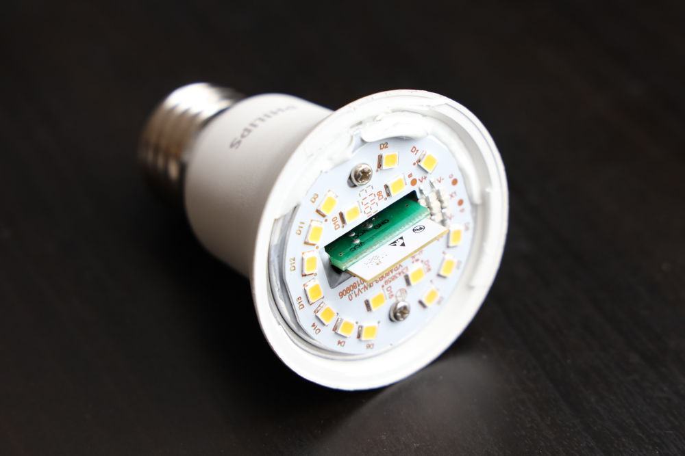
There are several versions of this lighbulb and I could not find anything about this particular version. The main differences seem to be the entire PCB and housing. Most of the older versions are accessible without much force.
I started by popping off the light diffuser. This takes just a bit of prying, since it is lightly glued to the base. After taking out two screws, the LED array can be unplugged and taken out of the assembly. This leaves the ESP antenna exposed, but the rest of the board is still inaccessible.
There is no way of getting into this particular model without a bit of cutting. I took my dremmel and cut out part of the almuninum casing/heatsink to get to the PCB. This made the important part of the board accessible and exposed all the relevant pins.
## Accessing UART
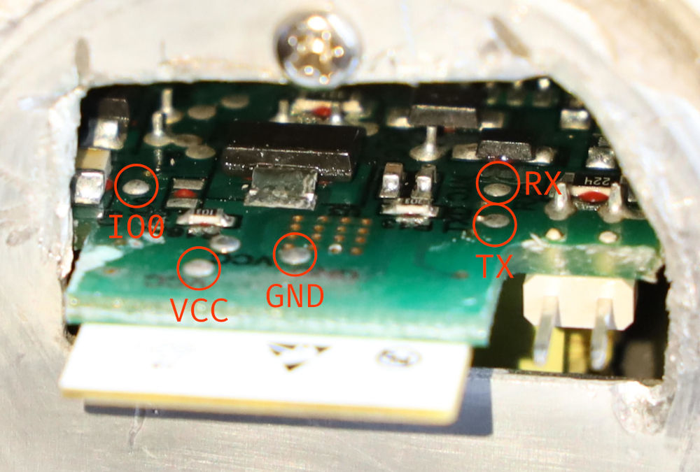
In order to be able to communicate with the device, we need to connect *RX* and *TX* pins, *3.3V* and *GND*. We also need access to the *IO0* pin used for enabling the UART download mode.

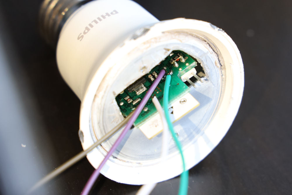
I soldered wires to the relevant pins and connected them to my USB-TTL programmer. Don't forget that *RX* and *TX* should be crossed, so *RX* on the ESP should lead to *TX* on the programmer.
To access the UART download mode, the chip has to have *IO0* pulled to ground during boot. This can be done simply by shorting the pin to ground.
## Building and flashing Tasmota
I used PlatformIO for the firmware compilation and flashing. You have to be a member of the `dialout` group in order to be able to access the device.
```sh
git clone https://github.com/arendst/tasmota/
cd tasmota
platformio run -e tasmota --target upload --upload-port /dev/ttyUSB0
```
After configuring basic network access, the firmware has to be set to *generic* and *GPIO15* to *PWM1*. Here is a configuration template:
```
{"NAME":"Xiaomi Philips","GPIO":[0,0,0,0,0,0,0,0,0,0,0,37,0],"FLAG":0,"BASE":18}
```
## Troubleshooting
I got suck for a long while at a problem where the ESP refused to respond or was sending invalid data. My first thought was to make both data wires shorter and set lower baudrate to eliminate noise, which did not help. I then tried to supply external power, as recommended in the [official troubleshooting documentation](https://docs.espressif.com/projects/esptool/en/latest/esp32/troubleshooting.html), without much luck.
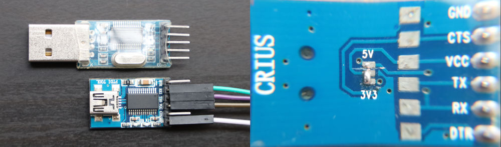
It turned out to be caused by the programmer itself. The first programmer I used had a `Prolific PL-2303HX` chip. The communication started working after using a different programmer with an `FTDI` chip and modifying it to output 3.3V instead of 5V. That can be done by simply cutting the default short between *5V* and the middle pin and creating a solder jumper from *3V* instead.
## References
-
-
-
-
-